
A conceptual sketches is more than just a labelled graphic.
It can be as simple as a series of drawings, concepts, and explorations, or as detailed as design images, suggestive plans, sections, and elevations, and 3D models of a development strategy.”
In this article you’ll learn:
- Purpose of conceptual sketches.
- Types of conceptual sketches.
- Merits and Demerits of conceptual sketches.
- Lots more.
So, if you’re ready to go with conceptual sketches., this article is for you.
Let’s get started!
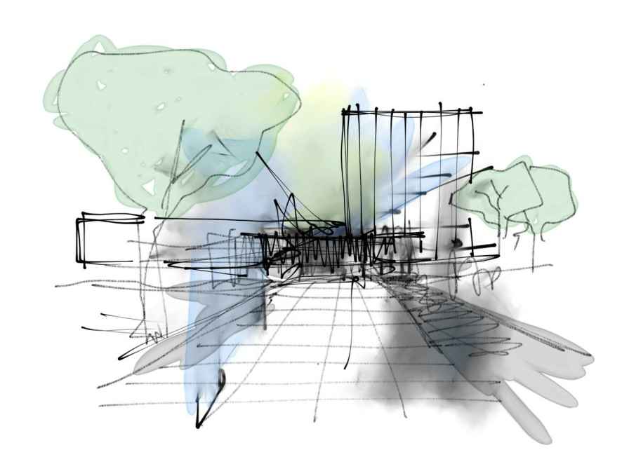
What are Conceptual Sketches?
Conceptual sketches are free-hand illustrations used by designers including architects, engineers, and planners to quickly and simply generate concepts.
Concept sketching may also be used to investigate more technical components of a design such as service arrangement, structure, the technique of construction, routes and shading, patterns and computations, etc.
Purpose of Conceptual Sketches:
- The concept sketch is a graphic illustration of the fundamental design and arrangement of a product.
- These preliminary drawings introduce the idea of allowing designers to design from this style of drawing before making detailed drawings or CAD models.
- Students can use this style of drawing to generate rough designs for their own design bikes.
- Concept sketches can also be used to investigate different areas of design offering preliminary answers to issues such as service organization, structure, method of construction, solar pathways and shade, prevailing winds, method of rotation, barriers, possibilities, and potential remedies.
- A sketch, ideas, and investigation, or significant in-depth thought, design descriptions, suggestive plans, sections, and locations, and a 3D model development process are all examples of concept design.
Architecture Concept Drawing:
The architectural conceptual sketches are an idea, clue, or concept that serves as the essential base and foundation of a design project and steers it forward.
It becomes the project’s progress and identity; it is continually updated at every level of the project’s growth.
The design of the finished object is represented by an architectural idea (complete building or structure).
It is growing in the same way that a seed does, hence it is the initial step in the design process.
Through its varied conceptual sketches, it adds diversity and outcomes to the project.
It is utilized to persuade clients of the design’s excellence.
It also assists the construction contractor in constructing on its base, and the task is completed fast and precisely.
They acts as a record of design & analysis plans.
Dimensions and Scale:
Scale is used to depict elements in architectural designs to appropriately depict the apparent size.
In order for the relative size to be presented accurately, the design is scaled to match the overall size of the building sheet.
The scale drawing’s measurements are measured to immediately “read.”
According to normal US architecture, the size of the sketch is as follows:
- ARCH A measures 9 x 12 inches (228 mm x 304 mm)
- ARCH B measures 12 x 18 inches (304 mm x 457 mm)
- ARCH C measures 18 x 24 inches (457 mm x 609 mm)
- ARCH D measures 24 x 36 inches (609 mm x 914 mm)
- ARCH E measures 36 x 48 inches (914 mm x 1219 mm).
Types of Conceptual Sketches:
Perspective Drawing:
Perspective sketching is a technique used to demonstrate perspective.
This illustration depicts a three-dimensional item on a two-dimensional plane.
Scale Drawing:
A sketch of an actual thing that has been shrunk or expanded by a given size.
Scaling is a drawing method that allows you to increase or decrease the size of an object dependent on the size of the design.
Production Drawing:
Production drawings are numerous comprehensive details drawings that provide various specifics regarding product manufacturing and processing.
Section Drawing:
The view of the building is depicted in such a way that it may be sliced into any portion in ‘Section Drawing,’ ‘Section,’ or ‘Sectional Drawing.’
Section drawing improves comprehension of structural information.
Site Plan:
A site plan is a large-scale drawing that displays the whole area of the intended project.
The required specification is also discovered in order to define the placement for the application plans.
Site plans are often produced following a site examination for conceptual sketches.
Technical Drawing:
Technical drawings are used to exchange ideas between industry and engineering. It is used to make designs more understandable.
The majority of individuals employ well-known symbols, views, units of measurement, notation systems, visual styles, and page layouts.
The technical diagram illustrates the requirement for particular communication in the production of a functional document.
Assembly Drawing:
Assembly drawings are used to depict the many components that make up a product.
The components appear to be compatible with one another.
And it can be depicted in drawings of orthogonal schemes, sections, and height, as well as three-dimensional views of integrated components, etc.
As-Built Drawings and Recorded Drawings:
After the construction process is completed, a built-up drawing is generated to depict the actual construction drawing.
Contractors typically use red ink to identify the ‘last construction problem.’
It is used to demonstrate to the client that the construction has been finished in a healthy and safe manner.
Furthermore, this design is utilized to demonstrate that the construction and maintenance work is done in accordance with the requirements for conceptual sketches.
Shop Drawing:
Contractors, distributors, manufacturers, subcontractors, advisors, and fabricators use shop drawings.
Even before the product is created, different construction papers, references to drawings and requirements, and so on assist the architect and engineer in designing their shop drawing.
Measurements, product conventions, and special manufacturing instructions should all be included in the shop design. Employees should be able to clearly interpret shop drawings.
Block Plan:
The block plan illustrates the layout of the structures in relation to the blocks on the map of the wider region. It also displays boundaries, highways, and other information.
This style of the graphic shows the development site and access in the red outline, as well as the developer’s land in the blue overview.
Engineering Drawing:
In engineering drawings, it is used to specify project-related specifications, construction materials, or a variety of other features.
The engineering drawing includes the technical drawings. Its purpose is to supply all of the necessary product information.
For engineering drawings, approved language and symbols are utilized for conceptual sketches, so that these sorts of graphics may be readily understood separately.
Location Plan:
The location plan is a document that goes with the drawing provided by the authority concerned as part of the planning procedure.
The location plan depicts the planned project in relation to its surroundings. This allows for accurate land identification by drawing on advanced ordnance survey (or equivalent) maps.
Floor Plan:
The floor plan shows how the house or land is laid out.
Floor plans illustrate the locations of walls, windows, doors, and stairs, as well as permanent fixtures such as bathroom fixtures, kitchen cabinets, and equipment.
The floor plan depicts various room kinds, room sizes, and wall lengths, among other things. This style of sketch might also include furniture layout.
Elevation:
This graphic is used to describe the building’s façade. The elevation of each structure is given in the compass direction in this picture.
An elevation is geometrically defined as a structure on a vertical plane. The vertical plane runs parallel to one of the building’s sides.
Cross Section:
A cross-section depicts a vertical plane by severing an object from a plane in conceptual sketches. This style of design aids in getting a better understanding of the building’s specs.
Isometric and Axonometric Projection:
On both dimensions, the isometric drawing is made at 30 degrees from the plan.
The link between distinct sides of an item can be demonstrated so that the complexities of the object’s form can be better understood.
The isometric sketch is created at 30 degrees from the plan in both axes.
Axonometric projection is used to present a drawing of an item at 45 degrees from the plane.
Detail Drawing:
“Demonstrates an item’s design, the assembly of object components, or the full system of assemblages.”
A thorough drawing depicts the part, the form, and the procedure.
The comprehensive design shows the details of a given size, kind of material, finish, durability, and any special shop instructions necessary for component manufacture, etc.
Drafting:
Drafting is a technical component.
Technical, architectural, or engineering drafting is performed. Accurate representations of items, buildings, or dwellings are also made.
It often contains a top view, main view, and side view of an item or structure. Budgets are frequently utilized as plans for building or assembly.
Computer-Aided Design:
CAD software is also used to enhance design efficiency, design quality, communication, and creativity.
When applied, design patterns generated by CAD software serve to increase quality.
The computer records the information electronically rather than making lines on paper. This system minimizes repetition.
This sketch helps identify mistakes. Additionally, it enables the effort to be made prior to completing the design.
What is the Difference between Sketching and Drawing?
Drawing is just the act of drawing marks on a surface. The two terms are frequently used interchangeably.
Sketches are often made as preliminary sketches in preparation for a more polished piece of art.
Sketches are frequently made with rapid markings and lack some of the nuances that a finished drawing would have.
Sketching is a quick record of a moments or a reminder to go further into anything. A sketch is more detailed and eventually becomes the completed piece.
Advantages of Conceptual Sketches:
- It improves your capacity to see what you’re looking at rather than relying on recollection or imagination to fill in the gaps.
- It enhances eye-hand coordination, which improves your ability to sketch what you see precisely.
- They teach your muscles how to behave in a specific way.
- This is an excellent approach to overcome composition difficulties or simply unwind.
- It’s a terrific approach to dealing with life’s circumstances both positive and negative for individuals who digest life visually.
Disadvantages of Conceptual Sketches:
- Sketching on a frequent basis is that if you are not cautious about drawing precisely, you may develop the habit of drawing poorly.
- No amount of time spent sketching is ever completely squandered.
Also read: Floor Space Index (FSI) | Town Planning | Carpet Area
Conclusion:
Conceptual sketches are typically inspired by the function, material, or philosophy of the structure by freehand in pencil or felt pen to allow for maximum freedom.
Because concept sketches are created at the beginning of the design process, there are few restrictions on what may be written down.
Related Posts
Rock Quality Designation(RQD): Building Strong Foundations
Spread Footing
Masonry Cement
Plain Cement Concrete
Concrete Efflorescence
Concrete Pile
Stepped Footing
Fineness Modulus of Coarse Aggregates
Difference between Condo and Apartment