
The spillway is a structure used to provide controlled release of water from a dam or levee downstream, usually on the banks of a dammed river. In the United Kingdom, they may be known as overflow channels.
For safety, the spillways must have sufficient flood discharge capacity, which is likely to occur during the lifetime of the dam.
Here we will learn about spillway, types of spillways & why spillway is provided in dam?
Introduction to Spillway:
The dam is a structure across the river to stop flowing water & to store it in the reservoir; the barrier could be a arch dam, rockfill dam, or earthen dam.
Spillways are provided at the top level of the dam.
Location of spillway:
- Spillways can be provided within the body of the dam.
- Sometimes spillways may be provided on one side or both sides of the dam.
- Sometimes a nearby spillways are provided which completely detaches from the dam.
Components of Spillway:
Approach channel:
The entrance structure or the path to draw water from the reservoir and convey it to the control structure.
It may be straight or curved in plan.
Its banks may be parallel, convergent, divergent, or combination of them and maybe vertical or sloping.
It may ensure minimum head loss through the channel to obtain uniformity of flow over the control structure.
Control structure:
A significant component of spillway provided with bridge and gates.
Regulates and controls the surplus water from the reservoir.
It does not allow the discharge of water below the fixed reservoir level.
Discharge carrier:
It is the waterway provides to convey tile flow released from the control structure to the downstream side of the spillway.
The cross-section may be rectangular, trapezoidal, or of other shapes.
Waterway may be broad or narrow, long or short.
Discharge channel:
They are provided to convey the water from the bottom of the discharge carrier to the downstream flowing river.
It may be the downstream face of the spillway.
The width of the discharge channel depends on the amount of water to be conveyed.
Enemy dissipators:
At the end of the discharge carrier, the water released from the control structure has high velocities to cause scour, thus energy dissipation is provided to avoid the scouring of the downstream side of the spillways.
These are to be provided before water entering the discharge channel.
The following are the different types of dissipators:
Bucket dissipators:
The high kinetic energy of water is reduced by providing a hydraulic jump at the end of the spillway.
The hydraulic jump can be achieved by providing bucket type dissipators.
By hydraulic jump of water some part of the energy is dissipated by aeration.
Stilling dissipators:
Stilling dissipators are usually provided after the buckets.
Due to the hydraulic jump of water, the water falling on the ground may cause cavitation’s on the ground.
These cavitations can be avoided by providing the stilling dissipators which consists of water, which reduces some part of the energy of water.
Baffle dissipators:
After passing the stilling basin, water still has some energy.
If any amount of energy exists, it can be entirely dissipated by providing baffle dissipators.
In this dissipators, structures are provided in several series depending on the amount of energy.
Types of spillway gates:
Straight drop spillway:
The straight drop spillway consists of a low elevation veal wall, the lower part of which is completely or nearly vertical.
When the water level within the reservoir rises above the mean pool level, the excess water freely falls from the crest of the weir, so it is known as a direct drop spillway or free overfill spillways.
To protect the beds, a synthetic pool with a concrete apron and a low secondary dam is constructed along the banks of the drift.
Proper ventilation must be provided beneath a falling jet to prevent the consequences of vibration and fluctuation.
Sometimes, an overhanging course is provided to the crest of the ridge, avoiding the entry of the small discharges to the ridge face.
Straight drop spillways are preeminently suited for the thin arch dams, earthen dams, or bunds.
Ogee Spillway:
The Ogee spillway signifies the shape of the weir’s drift face, it is a better form of straight drop spillway.
In this case, the lower part of the weir is personalized to the economical shape by the addition of a self-sufficiently falling water, which is an ogee shape.
The downstream face is mostly based on the principle of a projectile.
In general, the lower diaper size of the water jet will not be fixed for all water heads and due to this fact, the obtained method for the maximum head is considered when designing the Ogeee spillways.
Whenever there is surplus water, it will be dealt with independently of the Ogee-shaped crest through the Ogee spillway; therefore it can also be called an overflow spillway.

The Ogee spillway is most usually used in gravity, arch, buttress dam, etc.
For a gravity dam, it is usually located within the dam body.
The Ogee spillway is most usually used in gravity, arch, buttress dam, etc.
For a gravity dam, it is usually located within the dam body.
Shaft Spillway:
It is a type of spillway consisting of a vertical shaft, followed by a horizontal groove.
The surplus water enters the vertical axis, then into the flat drain, and finally reaches the channel drift; the beam formed is either artificial or natural.
Excavation for natural shafts is possible only when a hard rocky crust is present at the top.
The horizontal drain permits through the body or the foundation of the dam.
In the case of large projects, the inlet hole of the vertical shaft is specially shaped, called the morning glory or glory hole spillways.
Therefore, the shaft spillway is also called the morning glory spillway or bell-mouth spillway.
Shaft spillway is suggested if there is no space available for other types of spillways i.e., Ogee, straight drop spillway, etc.

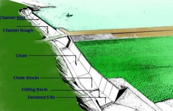
Chute Spillway:
It is a type of spillway in which surplus water flows through the sloping of the open channel.
It is often constructed at one end of the dam from a natural saddle of the river, which is separated by a barrier.
The Chute spillway is suitable for gravity dams, mud dams, rockfill dams, etc., but it is preferred when the width of the river valley may be very narrow.
The water flows along a slope or trough or an open channel and reaches the river.
This spillways also called trough spillways or open channel spillways.
The slope of the spillways is considered in such a way that movement must always be inside the supercritical state.
Energy dispersers are offered on a mattress of spills to dissipate energy from the falling water.
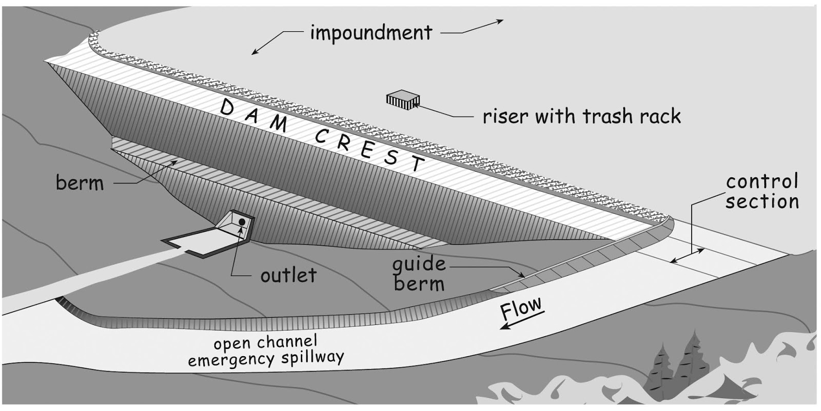
Side Channel Spillway:
It is very much similar to the chute spillway; however, the difference is the crest of the side-channel spillway is located on one side of it, while the crest of the side spillway is located between the side walls.
In different phrases, the dispersion of water from the crest is twisted to 90 degrees and move parallel to the crest of the side-channel spillway, as opposed to the spill.
Side-channel splits are generally preferred over chute spillways to avoid heavy cutting when adequate width flanks are not available.
The angle of flow of water can also be kept between 00 and 900 after passing the wear crest.
Siphon Spillway:
It is a kind of spillway in which surplus water flows by means of inverted U-shaped sewers.
Generally, it is prescribed inside the body or at the crest of the dam.
In each variety of siphon spillways, the air is pushed over the curved portion of the upper passage to stop water penetration when the water penetration level is below the mean pole level.
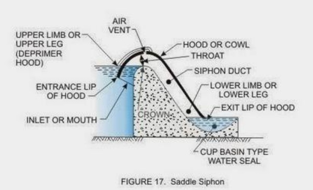
Whenever the level rises above the mean pool level, the water enters the drain and discharged by the siphonic action downstream of the channel.
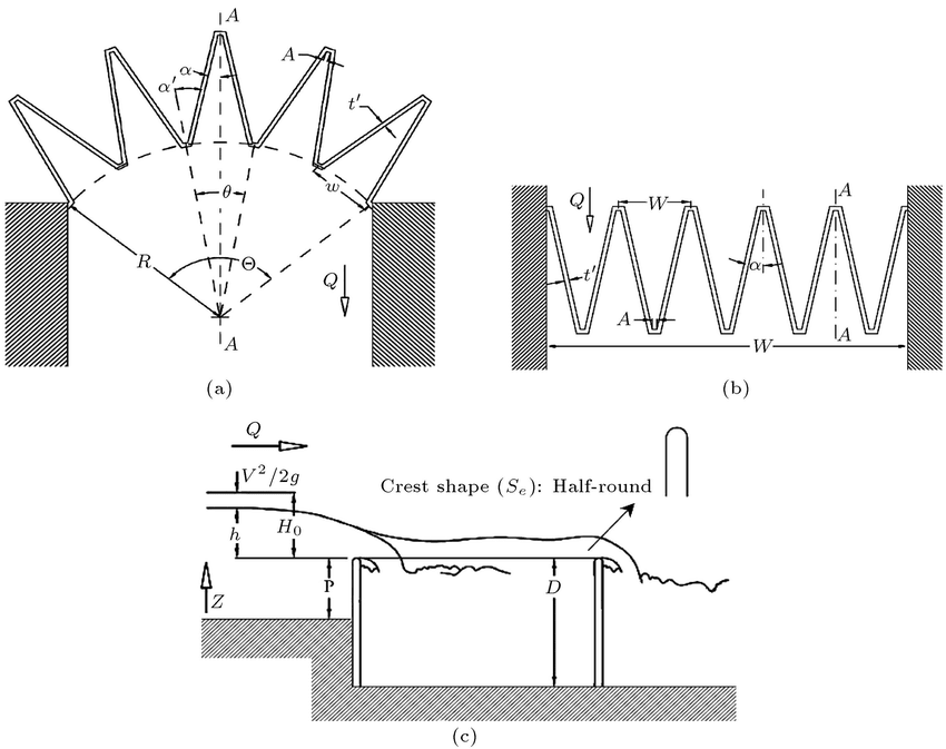
Labyrinth Spillway:
It is a type of spillway in which a wall is accidentally constructed to outspread the length of the damage with respect to the width of the channel.
This increase in insufficient length increases the discharge capacity of the weir and therefore the high water flow over the short head can quickly convey the drift.
Also read: River Training Works, Canal Lining & Shoring
OPEN CHANNEL FLOW | CROSS DRAINAGE WORK | RIVER TRAINING WORKS
Conclusion:
Hydropower projects includes flood-control structures designed for safely escape excess water from the reservoir.
This safety valve prevents water from spreading over the crest, taking the form of a spillway, weir or sometimes a combination of both.

Related Posts
Refresh Your Office: Simple Ideas to Boost Productivity and Motivation in Your Workplace:
Understanding the Nuances of Office Chair Vs Ergonomic Chair to Select Better!
Rock Quality Designation(RQD): Building Strong Foundations
Spread Footing
Masonry Cement
Plain Cement Concrete
Concrete Efflorescence
Concrete Pile
Stepped Footing